 Equipment
containing PCBs is still used even now, after the production
of PCBs itself has been forbidden. Especially the capacitor
of fluorescent lights cannot be disregarded. Although
there are just small amounts of PCBs in each capacitor,
they are numerous, and exist in familiar places, such
as in schools and in hospitals. Do PCBs leak from capacitors?
Is it really safe to use them? Equipment
containing PCBs is still used even now, after the production
of PCBs itself has been forbidden. Especially the capacitor
of fluorescent lights cannot be disregarded. Although
there are just small amounts of PCBs in each capacitor,
they are numerous, and exist in familiar places, such
as in schools and in hospitals. Do PCBs leak from capacitors?
Is it really safe to use them? |
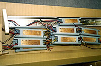
Structure of an internal capacitor
Photograph of an internal capacitor
In order to check whether PCBs volatilize from fluorescent
lights, two experiments were conducted in collaboration with
the Department of Engineering in the Tokyo University of Agriculture
and Technology (Masaaki Hosomi's laboratory) (Funakawa et
al., 2002).
- Investigation of ambient air pollution by PCBs in a room
where a fluorescent light capacitor containing PCBs is used.
- One capacitor is removed and put into a sealed-container
experiment system in order to measure the amount of PCBs
that volatilize from the stabilizer.
<Measuring of indoor air in which an equipment containing
PCBs is used>
According to the method for working-environment measurements,
air was sampled in a room where capacitors containing PCBs
were used (Fig. 1). Samples were taken continuously under
the following situations: for 3 to 4 days, all usable fluorescent
lights were turned on, air-conditioning was stopped, and
doors and windows were closed, and air was sampled. Samplings
were conducted twice, in September and in December 2001.
In addition, a sampling of the Department of Engineering
in the Tokyo University of Agriculture and Technology was
conducted as a control. Analysis was conducted by GC/MS.
(Fig. 1) Figure of the air sampling method
<The PCB concentrations were higher in the room
where equipment containing PCBs was used>
PCBs were not detected in the control room. However, PCBs
were detected in the room where the capacitors containing
PCBs were used (Table 1), at levels of 110 ng/m3 (September)
and 26 ng/m3 (December). It was then investigated whether
PCBs leak from a fluorescent light capacitor.
(Table 1)Observed PCB concentrations in the indoor
air(ng/m3)
 |
|
|
|
PCB
|
Control Site
|
JOF's
office |
|
|
Sep.
|
Dec.
|
|
|
|
|
Mono PCB
|
N.D. (<1.5)
|
N.D. (<2.0)
|
N.D. (<0.8) |
Di PCB
|
N.D. (<1.5)
|
34
|
3.0 |
Tri PCB
|
N.D. (<1.5)
|
62
|
20 |
Tetra PCB
|
N.D. (<1.5)
|
17
|
3.3 |
Penta PCB
|
N.D. (<1.5)
|
N.D. (<2.0)
|
N.D. (<0.8) |
Hexa PCB
|
N.D. (<1.5)
|
N.D. (<2.0)
|
N.D. (<0.8) |
Hepta PCB
|
N.D. (<1.5)
|
N.D. (<2.0)
|
N.D. (<0.8) |
Octa PCB
|
N.D. (<1.5)
|
N.D. (<2.0)
|
N.D. (<0.8) |
Nona PCB
|
N.D. (<1.5)
|
N.D. (<2.0)
|
N.D. (<0.8) |
Deca PCB
|
N.D. (<1.5)
|
N.D. (<2.0)
|
N.D. (<0.8) |
|
|
|
|
Total
PCB
|
N.D. (<1.5)
|
110
|
26 |
|
|
|
|
|
Control Site: Tokyo University of Agriculture
and Technology laboratory
JOF's Office: Using the PCB-containing Ballast
N.D.: Below Detection Limit
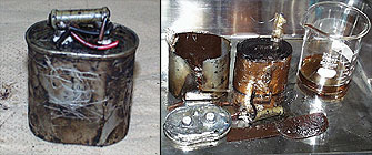
<Measurement of the amount of PCBs that volatilizes
from a capacitor>
The stabilizer containing PCBs (Matsushita Electric Works,
Ltd., made in 1970, product code: SNZ40211HB-7) was removed,
and sealed in a glass container (Fig. 2), after which the
amount of PCBs that volatilized in the air was measured
(Fig. 3). Temperature conditions were changed during the
experiments, 2.2, 15.5, 30 and 50 degrees centigrade, respectively.
<The fact that PCBs volatilized from a capacitor
was checked.>
As the temperature became higher, more PCBs volatilized.
Under the severest conditions of 50 degrees centigrade, 1
million/ng of PCBs volatilized from just one capacitor in
a day. A capacitor gets hot while in use. It becomes about
50 degrees centigrade in midsummer.
Moreover, in all temperature conditions, the PCBs (di-penta
chlorinated PCBs) with two to five chlorine molecules made
up the highest percentage of total concentrations. And since
this percentage mirrored the composition of the PCB product
(KC-300), the possibility that the capacitor containing PCBs
was the source of the indoor PCBs was further supported.
PCB volatilization rate from the PCB-containing ballast
using the volatilization chamber (ng/day)
|
|
|
|
|
PCB
|
Temperature
|
|
2.2
|
15.5
|
30
|
50 |
|
|
|
|
|
Mono PCB
|
N.D. (<4.0)
|
N.D. (<5.0)
|
N.D. (<160)
|
N.D. (<100) |
Di PCB
|
600
|
1100
|
8700
|
170000 |
Tri PCB
|
2000
|
3700
|
33000
|
680000 |
Tetra PCB
|
440
|
700
|
10000
|
180000 |
Penta PCB
|
14
|
16
|
230
|
5900 |
Hexa PCB
|
N.D. (<4.0)
|
N.D. (<5.0)
|
N.D. (<160)
|
N.D. (<100) |
Hepta PCB
|
N.D. (<4.0)
|
N.D. (<5.0)
|
N.D. (<160)
|
N.D. (<100) |
Octa PCB
|
N.D. (<4.0)
|
N.D. (<5.0)
|
N.D. (<160)
|
N.D. (<100) |
Nona PCB
|
N.D. (<4.0)
|
N.D. (<5.0)
|
N.D. (<160)
|
N.D. (<100) |
Deca PCB
|
N.D. (<4.0)
|
N.D. (<5.0)
|
N.D. (<160)
|
N.D. (<100) |
|
|
|
|
|
Total
PCB
|
3000
|
5500
|
37000
|
1000000 |
|
|
|
|
|
|
N.D. : Below Detection Limit
Comparison of PCBs in the sample
Summary
The results of these experiments suggest that PCBs volatilize
and spread when PCB containing capacitors that have deteriorated
or exceeded their product life were used. Stabilizers in
use are one source of PCB pollution, but since PCBs that
have volatilized from capacitors diffuse, the concentration
of PCBs detected in air is low. However, PCBs that escape
into ambient air pollute foods we eat through biological
accumulation, and these rebound upon us after all. This
should not be disregarded.
Continuing use of PCBs contributes to the risk of accidents
from exploding equipment, as well as other possibilities
of further contamination. Equipment containing PCBs that
is still in use should be collected immediately and treated.
|
